Train Kinetic Sculpture
 This project was a group project for my Introduction to Mechanical Prototyping class. We were given the project to create a kinetic sculpture that had something to do with the Victorian era. Now, what's the first thing that pops into your head when you think of the Victorian era? Trains right? Well maybe not but, that is what we wanted our structure to be. Additionally, the sculpture had to contain specific mechanical elements (i.e. a belt, a chain, 10+ sheet metal/acrylic parts, a cam/cam follower, a 4-bar linkage, 2 gear transmissions, etc.).
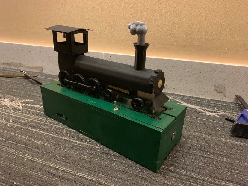
I worked mostly on the base for the train to sit on. The idea the group came up with was to have all the internal mechanisms for the train be driven through the wheels of the train. What this entailed was that the train would be resting on 2 "rails" (belts) that were driven by a motor. From there, the wheels would be driven by the rotating belts, turning a shaft inside the train and driving all the other elements of the sculpture.
This meant that I had to design mounts for the motor, spaces for a gear transmission from the motor to the belt drives, and all the parts for 2 belt drives. All these parts were pretty standard. For each belt drive there were two small, toothless, timing belt pulleys that were slightly raised from the top of the base. There were also two large pulleys that, when used in conjunction with a small, toothed pulley, created the tensioning system for the belt. That small pulley was connected to a shaft that, through a gear transmission, was powered directly by the motor.
Everything was modeled and assembled in SolidWorks before fabrication. The box itself was made from plywood cut with a CNC router, the shafts turned on a lathe, and the pulleys were 3D printed where necessary.